Ways to integrate MITIGATOR into the network
Terminology and methods for implementing the MITIGATOR DDoS protection system into the network.
External and internal networks
Logically MITIGATOR is connected to two networks:
- External network (external) – the network from which the traffic that needs cleaning comes;
- Internal network (internal) - the network in which the protected resources are located.
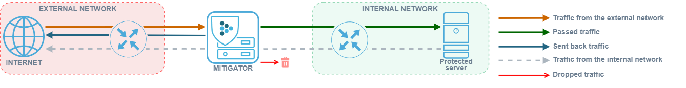
- Traffic from the external network - traffic coming to MITIGATOR from the external network. Consists of attack traffic and legitimate traffic.
- Passed traffic - traffic sent by MITIGATOR to the internal network. Consist of legitimate traffic.
- Reverse traffic - traffic that was generated by MITIGATOR and sent to external network. Reverse traffic is generated by active countermeasures, for example, using the challenge-response method sent by MITIGATOR to the internal network.
- Traffic from the internal network - traffic sent to the external network by the protected resource. This traffic can pass through the MITIGATOR but is not scrubbed.
- Dropped traffic - traffic dropped by MITIGATOR when clearing traffic from the external network.
Symmetric and asymmetric deployment schemes
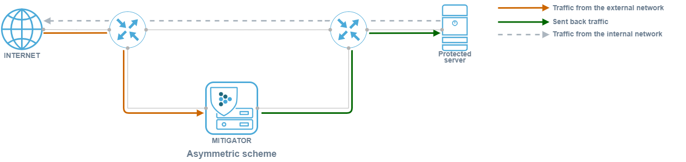
MITIGATOR can work with symmetric and asymmetric traffic routing.
With a symmetrical deployment scheme, traffic from the external network to the internal and vice versa passes
through the MITIGATOR.

With an asymmetric deployment scheme, traffic from the external network passes through MITIGATOR, and traffic from the internal network passes by. When using an asymmetric deployment scheme, no resources are spent on processing traffic on the internal network.
Defense methods
Defense methods can be divided into:
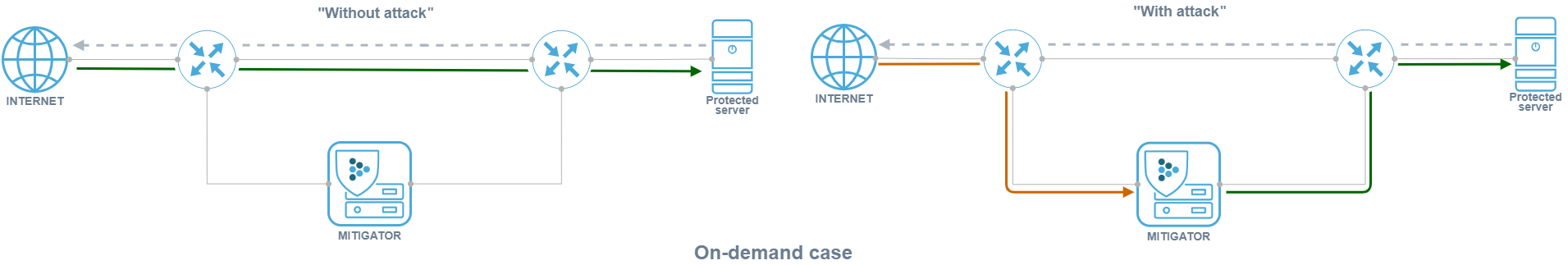
- “Always-on” – traffic from the external network always passes through MITIGATOR;
- “On-demand” – traffic from the external network is sent to MITIGATOR only
when necessary, for example, via BGP announcement from the MITIGATOR management interface.
Advantages of the “Always-on” method:
- Attack traffic is filtered as soon as it appears.
- No previously established sessions are reset.
- Detailed traffic statistics are collected.
Flaws of the “Always-on” method:
- Running countermeasures may affect legitimate traffic.
- Constant traffic redirection to protection may adversely affect
the optimal traffic routes. - A large volume of legitimate traffic constantly passing through the protection system loads it in the background.
In MITIGATOR, to reduce the impact on legitimate traffic and background load,
each countermeasure can be enabled individually only at the moment
an anomaly is detected. It takes 1+ second for the countermeasure to activate.
Advantages of the “On-demand” method:
- Without an attack, there is no impact on traffic.
- There is no constant load on the protection system.
Flaws of the “On-demand” method:
- Increased time interval between the beginning of an attack and the transfer of traffic to protection.
- Previously established sessions are reset.
- Lack of traffic statistics or inaccurate statistics collected over flow protocols.
To avoid resetting previously established sessions with the “On-demand” method a soft start mode is implemented in the MITIGATOR countermeasures.
Network integration at the physical level
MITIGATOR can be connected to the network in two ways at the physical level:
- “Inline” – “into the gap” in the network, when traffic from the external network comes through one kind of physical network interfaces and goes to the internal network through others.
- “On-a-stick” – traffic from the external and internal networks passes through the same network interface. Belonging to an external or internal network is determined by the VLAN ID.
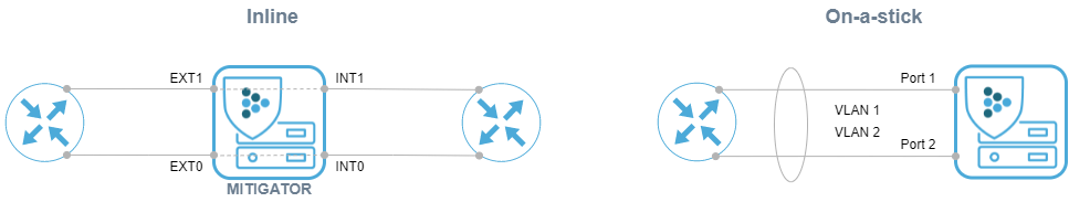
When connecting “Inline”, the network from which the frame arrived is determined by the physical port from which the frame was received: “ext” ports – external network, “int” ports – internal network. Inside the system, “ext” and “int” ports are switch in pairs and the frame – is sent from the port with the same number as the receiving port. Both traffic with VLAN ID and without it is processed.
When choosing the “On-a-stick” connection method, a traffic re-tagging table is set, consisting of pairs of external and internal VLAN IDs. A frame with an external VLAN ID received from any physical port is considered as coming from an external network. The processed frame is sent to the internal network over the same port through which it was received, and its VLAN ID is replaced with the corresponding internal one. If the incoming frame contains a VLAN tag with an internal VLAN ID, it is replaced with the corresponding external VLAN ID, and the frame is sent through the same port.
Network integration at the network layer
At the network level, MITIGATOR can be L2-transparent or act as an L3 device with limited functionality.
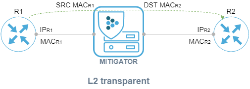
In the “L2 transparent” mode, MITIGATOR is invisible to surrounding network devices
and does not affect the interaction at the network level in any way. The frame passing through the
MITIGATOR is not changed.
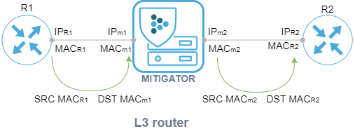
In the “L3 router” mode, the system performs a number of basic functions of an L3-device, which allows routers in connected networks to use MITIGATOR as a next-hop and act as next-hop for MITIGATOR using IPv4 and IPv6 protocols.
It is assumed that there is a router in the external network to which the MITIGATOR is connected. An internal router is located in the internal network. When a frame arrives from the external network, the frame’s source MAC address is replaced with the MAC address of the MITIGATOR’s internal interface, and the destination MAC address is replaced with the MAC address of the internal router. For frames from internal network, the MAC addresses are reversed.
Own routing parameters can be set for each pair of VLAN IDs in “L3 router” mode.
The system supports the functions of the ARP and NDP protocols
To determine the MAC addresses of neighboring routers. The IP addresses of the MITIGATOR interfaces and the IP addresses
of the internal and external routers are set. MITIGATOR sends requests to resolve the MAC addresses of routers
once every 30 seconds. Polling parameters are set in the configuration file
data-plane.conf (description). The MAC addresses
of the external and internal interfaces of MITIGATOR can be set manually.
Also, the MITIGATOR packet processor can respond to ping messages.
Until the process of resolving the MAC addresses of neighboring routers is completed, all frames are dropped. Frames that are not addressed to the MITIGATOR’s internal or external MAC address are always dropped.
Features of the schemes
The MITIGATOR can be connected to the network in four ways:
Inline L2 transparent:
- Only IPv4 and IPv6 is processed, the rest is passed without being processed.
- VLAN stays the same.
- LACP works between network devices via MITIGATOR.
On-a-stick L2 transparent:
- Only IPv4 and IPv6 traffic is processed, the rest is passed without processing.
- VLAN ID is retagged.
- Frames with a VLAN ID not present in the retagging table are dropped.
- Only static LAG is supported.
Inline L3 router:
- Only frames whose dst MAC belongs to MITIGATOR are processed, the rest are dropped.
- Only static LAG is supported. Two separate LAGs are assembled for the external and internal networks.
On-a-stick L3 router:
- IP addresses can be set for each VLAN pair.
- Only frames whose dst MAC belongs to MITIGATOR are processed, the rest are dropped.
- The MAC addresses of the external and internal interfaces of MITIGATOR can be set manually.
- Frames with a VLAN ID not present in the retagging table are dropped.
- Only static LAG is supported.
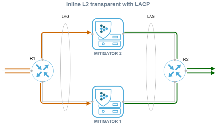
Horizontal scaling
For the Inline L2-transparent deployment method, traffic balancing between MITIGATOR instances is possible due to LACP between R1 and R2.
For the L3 router deployment method, it is possible to balance traffic between MITIGATOR instances using ECMP.
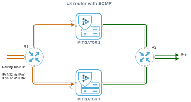
In all cases, balancing across MITIGATOR instances must be configured
so that the src_ip + dst_ip pair always hits the same device.
Centralized management of multiple instances of MITIGATOR is possible in cluster mode
Schematic diagrams of the cluster and settings are described in
separate section.
Ensuring network connectivity in case of accidents and scheduled work
To ensure network connectivity in case of accidents and scheduled work, you can use:
- L3 router balancing scheme with ECMP and route announcement via BGP;
- Inline L2-transparent balancing scheme with LACP;
- Inline L2 transparent scheme with hardware bypass.
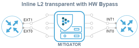
MITIGATOR supports network interfaces with Hardware Bypass. Their use allows you to maintain network connectivity in the event of a power outage or a software error in the packet handler. For scheduled jobs, you can control the Bypass operation mode via the Web interface.
Using Collector to detect attacks
If, in the absence of an attack, traffic does not pass through the MITIGATOR, then detection requires receiving telemetry on traffic from network equipment. Telemetry from the upstream router is sent to Collector via flow protocols. Collector sends traffic statistics to MITIGATOR. The detection subsystem in MITIGATOR, having detected an anomaly, sends a BGP announcement to redirect traffic for cleaning.
Such interaction may be set up also with third-party flow collectors.
Application of GRE tunneling
GRE tunneling can be used in MITIGATOR in two scenarios:
-
For service provider of DDoS protection service.
The provider provides a service to a consumer that is outside its network, or the delivery of cleared traffic to the protected resource is complicated by the peculiarities of routing in the provider’s network. In this case, traffic arrives at MITIGATOR from the external network, undergoes cleaning, after which it is packed into a GRE tunnel and sent to the protected resource in the external network. Outgoing traffic of the protected server can be packed into a GRE tunnel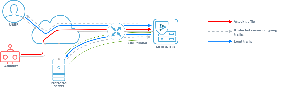
or sent directly to the user over the Internet.
-
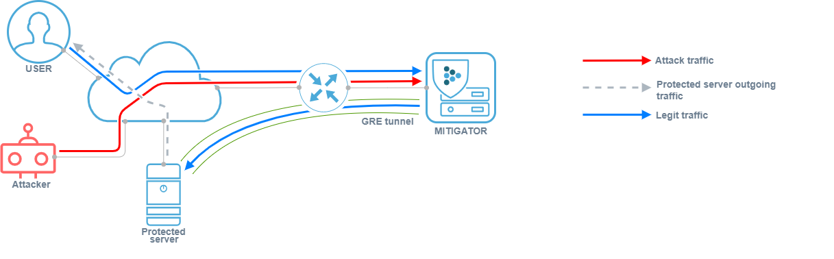
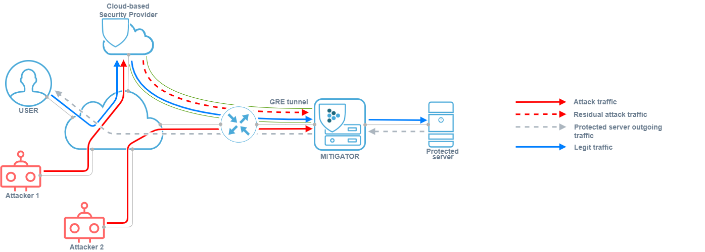
For service consumer of DDoS protection service.
The consumer does not have a direct connection to the service provider’s network, or the service provider is having difficulty delivering traffic. In this case, the traffic enters the MITIGATOR through the GRE tunnel, is unpacked and cleaned, and then sent to the protected resource on the internal network. Outgoing traffic of the protected server can be packed into a GRE tunnel.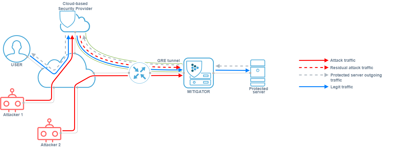
or sent directly to the user over the Internet.
Network deployment example
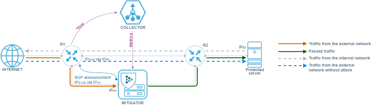
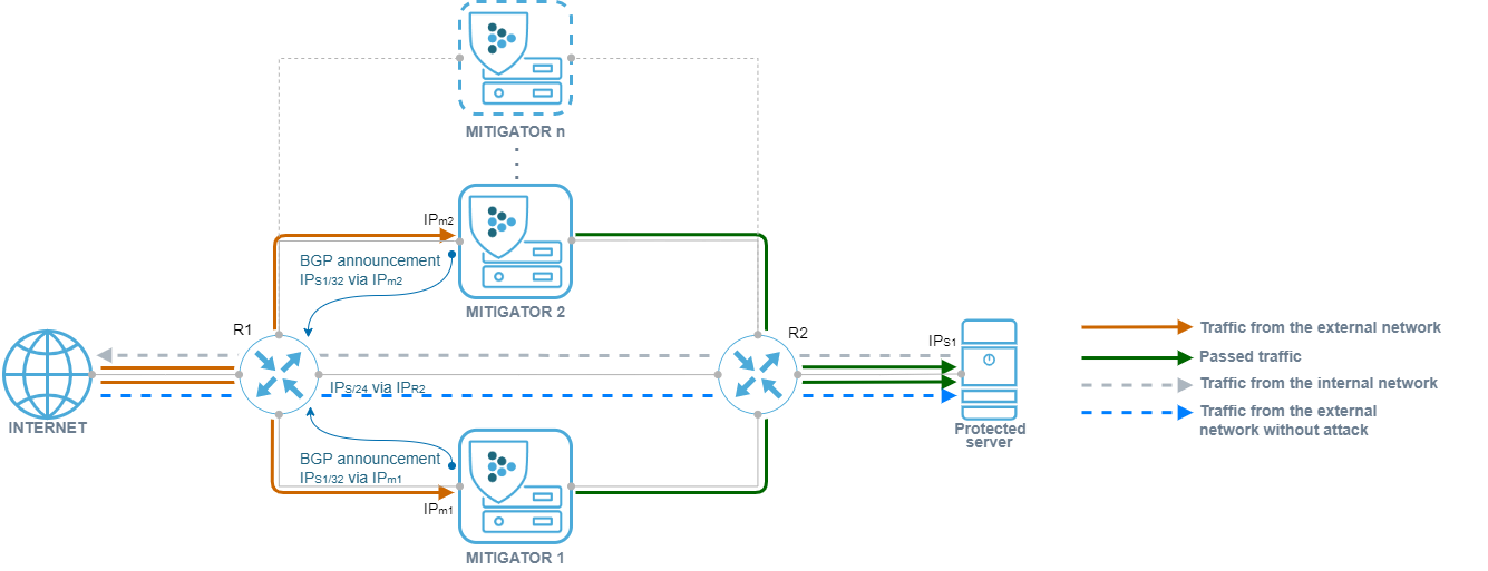
Asymmetry + On-demand/Always-on + L3-inline + BGP announcement
Let’s consider an asymmetric implementation of several instances of MITIGATOR, in which both protection scenarios can be used simultaneously.
A route is set on router R1, according to which the IPs / 24 prefix is available through router R2, ECMP support is enabled, balancing is configured so that the src_ip + dst_ip pair falls on the same next-hop. MITIGATOR is assembled into a cluster. Each MITIGATOR instance has established a BGP session with R1. R2 has a default route set to R1.
Thus, if there is no need for protection, traffic to the protected resource comes directly from R1 to R2, bypassing the MITIGATOR. At the moment when it is necessary to activate protection, MITIGATOR instances send a BGP announcement to R1 stating that the protected IPs1/32 prefix is available over IPm1 and IPm2. Due to ECMP balancing, traffic will be distributed between two devices.
This deployment option allows to:
- increase fault tolerance;
- horizontally scale the cluster to improve performance;
- protect targeted resources;
- if necessary, allow traffic to MITIGATOR in the “On-demand” mode, or remove the protection from traffic in the “Always-on” mode;
- Simplify maintenance and troubleshooting.