MITIGATOR in Cluster Mode
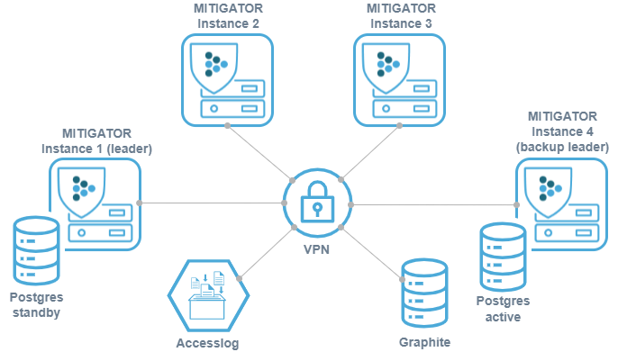
In cluster mode, several instances of the MITIGATOR system use common databases and are centrally managed. By adding additional instances, the system allows unlimited scaling. Cluster mode allows you to process traffic independently on each instance, but manage them from a single interface. In the event of a planned or emergency shutdown of any instance, the ability to manage the rest remains.
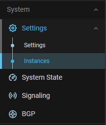
Deployment
Virtual network (VPN) is configured between instances. It needs network connectivity between instances to work. Detailed information on setting up and the necessary access is available by the link.
It is important to set up traffic balancing between instances so that the src_ip + dst_ip pair always hits the same device. Otherwise, senders may fail active MITIGATOR countermeasure checks.
There are several principal deployment schemes.
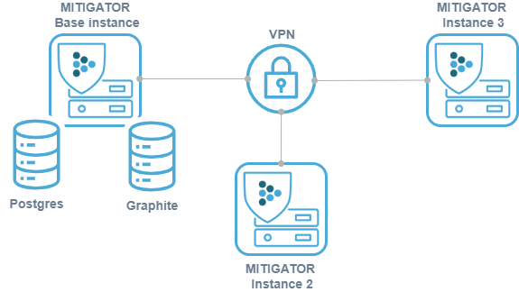
-
+ easy set up;
− shutting down the master instance leads to a loss of management and monitoring;
− data is lost if the master disk fails. -
Internal fault-tolerant storage:
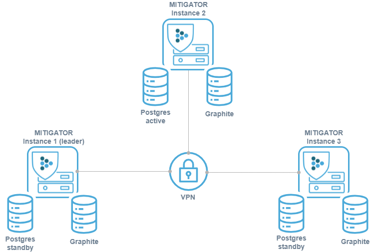
+ fault tolerance due to database replication;
+ no need for an additional server for storage;
− resources of MITIGATOR instances are spent on storage needs;
− increased requirements for administrator qualifications;
− lack of customization flexibility. -
External fault-tolerant storage:
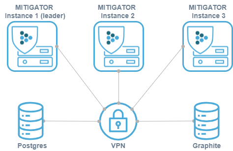
+ Full control and flexibility (Fault-tolerance, fine tuning);
+ the load is removed from MITIGATOR instances;
− qualified administrator required;
− additional server needed for storage;
− migration needs to be run manually when upgrading. -
The above implementation schemes can be combined with each other, the pros and cons of this method combine the pros and cons of the schemes separately.
Management via web-interface
The main change in the MITIGATOR interface when switching to cluster mode is the division of some settings into those related to the system as a whole and designed for specific instances.
On the “Instances” tab, the user has a list of all system instances. For each of them, the current activity status is displayed. The switches centrally change the state of the instance. Clicking on the instance name takes the user to the instance setup page. If only one instance has been created in the system, then when clicking on the “Instances” menu item, the user will immediately go to the instance settings page.
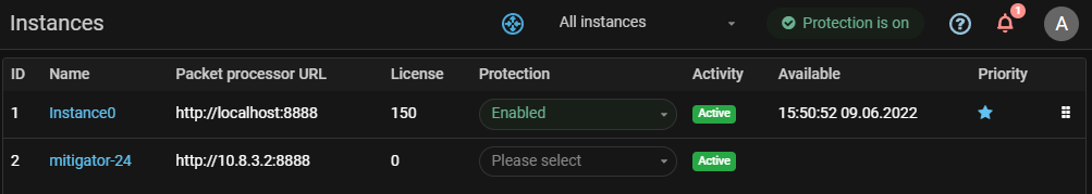
In the instance settings, its name, leader attribute, protection status, and address of the packet processor for this instance can be changed.
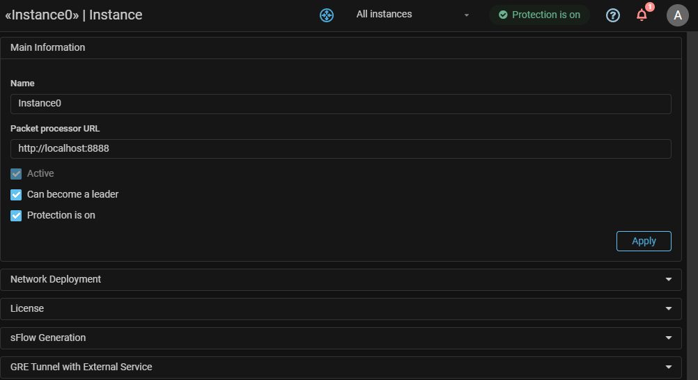
The “Network integration” and “GRE tunnel with 3rd party service” sections are now on the “Instances” tab, because for the system to work correctly, network deployment parameters must be set for each instance.
MITIGATOR allows you to use link aggregation (LAG) between devices in the external and internal network.The network integration settings affect which link aggregation options can be used:
- in “L2 Transparent” mode — static or dynamic (i.e LACP);
- in “On-a-stick” mode — only static LAG.
MITIGATOR allows you to balance the load between several system instances via ECMP by announcing the same prefixes to each instance via BGP. When one of the instances shuts down, the announcement is removed and traffic is automatically distributed among the remaining instances.

“License” card is separated in two parts. The system settings set the value of the license key, and the instance settings contain the licensed band controls and service information.
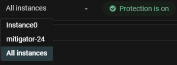
In the upper panel of the interface there is a drop-down list that allows you to select an instance for which the system will display charts. It is also possible to display a summary of all instances if “All instances” is selected.